In a simple circuit that is used to light a bulb with a battery, the battery provides direct current—a current flowing in only one direction. This article is concerned with the analysis of simple direct current circuits of two types: (1) those with combinations of resistor elements and (2) those with batteries in different branches of a multiple‐loop circuit.
Resistance, at least to some degree, exists in all electrical elements. The resistors might be light bulbs, heating elements, or components specifically manufactured for their resistance. It is assumed that the resistance in the connecting wires is negligible.
The series connection of two resistors ( R 1 and R 2) is shown in Figure 1. What is the equivalent resistor for this combination?
Figure 1
Two resistors connected in series. The drawing (a) is equivalent to the schematic (b).
Because there is only one pathway for the charges, the current is the same at any point in the circuit, that is, I = I 1 = I 2. The potential difference supplied by the battery equals the potential drop over R 1 and the potential drop over R 2. Thus,

When resistors are in series, the equivalent resistance is the sum of the individual resistances. Compare this result with adding capacitors in series. For series resistors, the current is the same; while for series capacitors, the charge is the same. (Note that the equivalent resistance is a simple sum, but the equivalent capacitance is given by a reciprocal expression.)
The parallel connection for two resistors ( R 1 and R 2) is shown in Figure 2. What is the equivalent resistance for this combination?
A circuit illustrating the application of Kirchhoff's rules, and the resulting equations.
Figure 2
Two resistors connected in parallel. The drawing (a) is equivalent to the schematic (b).
At point a for the circuit diagram—see Figure (b)—the current branches so that part of the total current in the circuit goes through the upper branch and part through the lower branch. The potential drop of the current is the same regardless of which path is taken; therefore, the voltage difference is the same over either resistor ( V batt = V 1 = V 2). The currents sum to the total current:  from Ohm's law,
 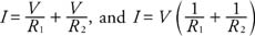 therefore,
Thus, the reciprocal of the equivalent resistance is equal to the sum of the reciprocals of the individual resistors in the parallel combination. Compare this result with adding capacitors in parallel. For parallel resistors, the voltages across the resistors are equal, and the same is true for parallel capacitors. (Note that the equivalent resistance is a reciprocal expression, but the equivalent capacitance for parallel combination is a simple sum.)
If a circuit has several batteries in the branches of multiloop circuits, the analysis is greatly simplified by using Kirchhoff's rules, which are forms of conservation laws:
- The sum of the currents entering a junction must equal the sum of the currents leaving the junction. This rule, sometimes called the junction rule, is a statement of conservation of charge. Because charge neither builds up at any place in the circuit nor leaves the circuit, the charge entering a point must also leave that point.
- The algebraic sum of the drops in potential across each element around any loop must equal the algebraic sum of the emfs around any loop. This rule expresses conservation of energy. In other words, the charge moving around any loop must gain as much energy from batteries as it loses when going through resistors.
When applying Kirchhoff's rules, use consistent sign conventions. Refer to the directions selected for the currents in Figure . Fewer mistakes will be made if one direction is consistently used—for example, clockwise in all loops. If an incorrect direction for one current is selected initially, the solution for that current will be negative. Use the following sign conventions when applying the loop rule:
- If the resistor is traveled in the direction of the current, the change in potential is negative, and if traveled opposite to the selected direction of the current, it is positive.
- If a source of emf is traveled in the direction of the emf (from – to + between the terminals), then the change in potential is positive, and if traveled opposite to the direction of the emf, it is negative.
Check the equations for Figure 3.

| Figure 3 |
A circuit illustrating the application of Kirchhoff's rules, and the resulting equations.
|
|
Imagine that the values of the resistances and voltage were given for this problem. Then, it would be possible to write four different equations: the junction equation, the top loop, the bottom loop, and the outside loop. Only three currents exist, however, so only three equations are necessary. In this case, solve the set of equations that are the easiest to manipulate.