Resistor-capacitor circuits
A circuit with a resistor, a capacitor, and an ac generator is called an RC circuit. A capacitor is basically a set of conducting plates separated by an insulator; thus, a steady current cannot pass through the capacitor. A time‐varying current can add or remove charges from the capacitor plates. A simple circuit for charging a capacitor is shown in Figure 2.
| Figure 2 |
An RC circuit for charging a capacitor.
|
|
Initially, at time t = 0, the switch (S) is open, and there is no charge on the capacitor. When the switch is closed, a current will pass through the resistor and charge the capacitor. The current will cease when voltage drop across the capacitor equals the potential of the battery (V). Once the capacitor reaches the maximum charge, the current will decrease to zero. The current is at maximum immediately after the switch is closed and decreases exponentially with time. The capacitive time constant (τ), the Greek letter tau) is the time for the charge to decay to 1/ e of its initial value, where e is the natural logarithm. A capacitor with a large time constant will change slowly. The capacitive time constant is τ = RC.
From Kirchhoff's rules, the following expressions for the potential difference across the capacitor (V C) and the current (I) in the circuit are derived:
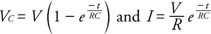
where V is the potential of the battery.
Resistor-inductance circuits
A circuit with a resistor, an inductor, and an ac generator is an RL circuit. When the switch is closed in an RL circuit, a back emf is induced in the inductor coil. The current, therefore, takes time to reach its maximum value, and the time constant, called the inductive time constant, is given by

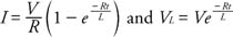
The equations for the current as a function of time and for the potential across the inductor are
A switch was used in the above discussions of RC and RL circuits for simplicity. Opening and closing a switch gives a response similar to that of an ac current. The RC and RL circuits are similar to each other because an increase in voltage yields a current that changes exponentially in each circuit, but the responses are different in other ways. These different behaviors, described below, lead to different responses in ac circuits.
Reactance
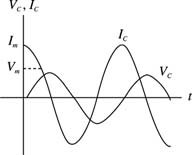
Now consider an ac circuit consisting only of a capacitor and an ac generator. The plots of current and voltage across the capacitor as a function of time are shown in Figure . The curves are not in phase as they were for the circuit of a resistor and an ac generator. (Refer to Figure .) The curves indicate that, for a capacitor, the voltage reaches its maximum value one quarter of a cycle after the current reaches its maximum value. Thus, the voltage lags the current through the capacitor by 90 degrees.
The capacitive reactance (X c) expresses the impeding effect of the capacitor on the current and is defined as

| Figure 3 |
Current and voltage from an ac source through a capacitor.
|
where C is in farads and the frequency (f) is in units of hertz. Ohm's law yields V c = IX c , where V c is the rms voltage across the capacitor and I is the rms current in the circuit.
Consider a circuit with only an inductor and an ac generator. Figure shows the plots of the current and voltage as a function of time for the inductor. Note again that the voltage and current are not in phase. The voltage for this circuit reaches its maximum value one quarter of a cycle before the current reaches its maximum; thus, the voltage leads the current by 90 degrees.
| Figure 4 |
Current and voltage from an ac source through an inductor.
|
|
The current in the circuit is impeded by the back emf of the inductor coil. The effective resistance is called the inductive reactance (X L) defined by (X L) =2π fL, where L is measured in henries and f is in hertz. Ohm's law yields (V L) = IX L , where (V L) is the rms voltage across the inductor and I is the rms in the inductor.
Resistor-inductor-capacitor circuit
A circuit with a resistor, an inductor, a capacitor, and an ac generator is called an RLC circuit. The phase relationships of these elements can be summarized as follows:
- The instantaneous voltage across the resistor V R is in phase with the instantaneous current.
- The instantaneous voltage across the inductor V L leads the instantaneous current by 90 degrees.
- The instantaneous voltage across the capacitor V c lags the instantaneous current.
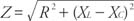
Because the voltages across the different elements are not in phase, the individual voltages cannot be simply added in ac circuits. The equations for the total voltage and the phase angle are
where all voltages are rms values. Ohm's law for the general case of ac circuits is now expressed V = IZ, where R is replaced by impedance ( Z), measured in ohms. The impedance is defined as