Capacitors

A capacitor is an electrical device for storing charge. In general, capacitors are made from two or more plates of conducting material separated by a layer or layers of insulators. The capacitor can store energy to be given to a circuit when needed.
 

Capacitance

The capacitance (C) is defined as the ratio of the stored charge (Q) to the potential difference (V) between the conductors:


Capacitance is measured in farads (F) and 1 farad

Parallel plate capacitor

In its simplest form, the capacitor is a set of oppositely charged parallel plates separated by a distance (d). From the equation for the potential difference of parallel plates and the definition of capacitance, the capacitance for parallel plates is


Strictly speaking, this equation is valid only when there is a vacuum between the plates.

When a nonconducting material is placed between the capacitor plates, more charge can be stored because of the induced charge on the surface of the electrical insulator. The ratio of the capacitance with the insulator to the vacuum capacitance is called the dielectric constant (κ, the Greek letter kappa). The values for the dielectric constants can be found in tables of properties of materials. The equation for the parallel plate capacitor with a dielectric that fills the space between the plates is

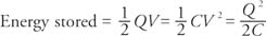
The energy stored in a capacitor can be found by any of the following three equations, which are each in terms of different variables:


Parallel and series capacitors

Capacitors can be connected either in parallel or in series. Two capacitors are in parallel if the negative plates are connected and the positive plates are connected, as shown in Figure 1.

Figure 1

Two capacitors connected in parallel. The drawing (a) is equivalent to the schematic (b).


An equation can be derived for the capacitance of one capacitor that would have the equivalent capacitance of these two capacitors. The total charge stored on the two capacitors is Q = Q 1 + Q 2. The voltage across each capacitor is the same and is equal to the voltage of the battery (V); therefore, Q 1 = C 1 V and Q 2 = C 2 V, or for the equivalent capacitor, Q = C eq V. Substituting into the equation for total charge yields C eq V = C 1 V + C 2 V, or C eq = C 1 + C 2. This result can be generalized to state that the equivalent capacitance for a set of capacitances in parallel is simply the sum of the individual capacitances.

Capacitors are connected in series if the positive plate of one is connected to the negative plate, as shown in Figure 2.

Figure 2

Two capacitors connected in series. The drawing (a) is equivalent to the schematic (b).


In series combinations, all the capacitors have the same charge. The potential differences across the capacitors add to equal the potential difference between the terminals of the battery; therefore, 


Substituting these equations into the equation for potential difference gives 


Canceling the charge gives the following expression for the equivalent capacitance for series combinations: 


Note: A common mistake in calculating series capacitance is to forget to take the reciprocal to find the equivalent capacitance after adding the reciprocals of the individual capacitors.


Back to Top
×
A18ACD436D5A3997E3DA2573E3FD792A